By Rob — Tue, 17 Nov 2015
After months of toil the digger prototype is now complete. The digger started as "let's take this controllable toy digger, and cut the controller off it". Now, we have a working prototype, allowing for a user to control the digger via the internet. You can see the controls here, but you'll need to get access from us to actually run it at this stage.
This project has taught me heaps about electronics and 3D printing, and let me flex my programming muscles in new ways.
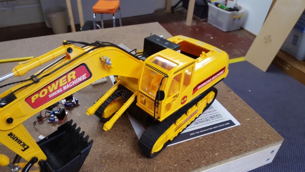
Here is what it looks like at the moment.
The toy digger works off a number of motors that control the arm movement, tracks, and rotation. These motors work quite simply -- if you put current in one way, the motor goes one way. Reverse the current, and you reverse the direction of the motor.
Our goal was to use a Particle Core as the main controlling component, turning switches on or off to set the motors one way or another. The project ended up being lots of testing, reworking, and tinkering, to come up with the final solution.
To get started, we developed a circuit that lets us perform the current-switching requirement.
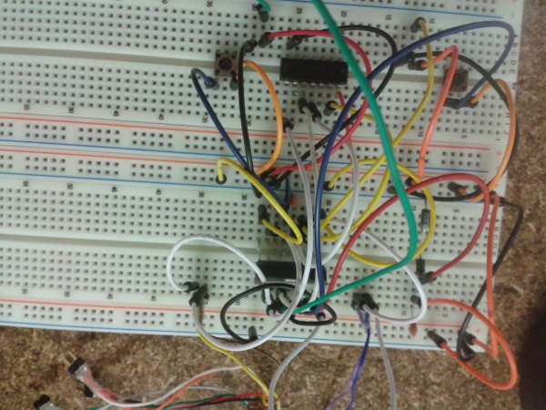
Losing track of wires is an issue at this stage.
Once we had that complete, @firnsy found a motor controller board that did the same thing. This drastically simplified the process, allowing us to control the motors from the Particle Core, a few NOT gates, and these motor controller boards.
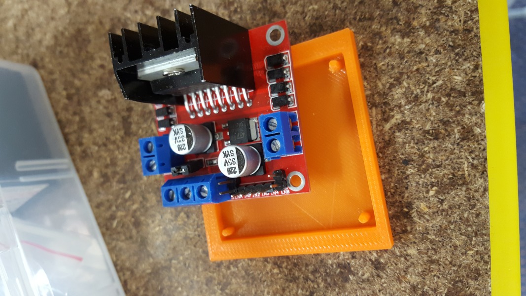
Life is much easier when there is a circuit board that does what you want. Orange bit to be explained soon.
The motor controller works by having an enable pin, and two direction pins. Only one of the direction pins should have 5V in at a given stage. Either the enable pin activated, the direction pin dictates which direction the (12V) of power goes to the motor. Each motor controller has two sets of these, each separately handling a different motor.
We managed the "only one direction pin at a time" problem using a NOT gate, specifically the 74HC04N chip, which gives us 6 of these (handy, as we need 5). We have a signal input (coming from the Particle Core) heading into the input of a NOT gate. The Input, and the NOT output, are then sent to each direction pin for a given motor.
This all handily fits on a breadboard, which we are planning to use for a while, at least until I learn how to use the CNC machine to make my own circuits.

The Particle Core connects to the 74HC04N chip, the 74HC04N chip connects to the motor controller...
Of course, the Particle Core takes 5V in, and the motors take 12V in. To fix this, we use a 12V battery and then a regulator to reduce the power. Of course, I did screw this up at one point, sending 12V straight to the Particle Core, blowing the fuse and getting a nice puff of smoke.
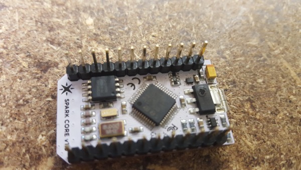
I owe @firnsy a new Particle Core. Notice the mark on the IC to the right.
It was a goal of this project to eventually make the digger accessible via a website, much like our lights are.
Ignoring the obvious tripping hazard, I wanted to make sure there was some separation between what the general public can input, versus what happens to the digger. We didn't want it constantly running into something, blowing the motor or similar.
For this reason, the core was programmed to take simple inputs, like "forwards", and then a function on the core will translate that into a more specific action like "go forwards for 3 seconds and then stop".
The Core's programming, at least as far as running the tracks to move is concerned, is built around the following function:
int _run_tracks(int iterations, bool left, bool right, int on_multiplier){
    // Runs tracks however they are setup
    int result = 0;
    for (int jn=0; jn< iterations && result == 0; jn++){
        for (int i=0; i<CYCLES_TO_RUN; i++){
            if (left) digitalWrite(LEFT_TRACK_ENABLE, HIGH);
            if (right) digitalWrite(RIGHT_TRACK_ENABLE, HIGH);
            delay(TIME_ON * on_multiplier);
            if (left) digitalWrite(LEFT_TRACK_ENABLE, LOW);
            if (right) digitalWrite(RIGHT_TRACK_ENABLE, LOW);
            delay(TIME_OFF);

            if (eStop == true){
                //return 1;  // Note: remember to set motors low
            }
        }
    }
    return 0;
}
This does a few things. First, it allows you to turn on either the left or right (or both) tracks. It also lets you dictates the number of iterations to go for, which means you can set some actions to just go longer. For instance, turning takes a bit of time, so we have that a little longer that just going forwards.
This code also does PWM (Pulse Width Modulation). We found that just turning the motors on full was a bit... crazy... so we decided on turning them on and off really fast instead. At present, TIME_ON is 10 milliseconds, and TIME_OFF is 20 milliseconds. The following GIF slows this down (100 on, 200 off) to show what this code is doing:
Digger tracks moving at a slowed down pace (but still the same ratio).
The API itself is just a Flask app (written in python 3), that provides some buttons that subsequently call the functions provided by the core. All of the code, including the core code and Flask app, are available on the Ballarat Hackerspace Github page. The web API calls Flask functions, which in turn call the exposed functions from the Particle Core. This indirect manner gives us some security, as it means people can't send arbitrary commands straight from the web interface. Most of the security is handled by the fact that you will need an access token to run the commands.
Keep an eye out for more exciting digger-based adventures in future posts!